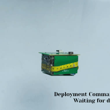
Design Process of the Deployable Solar Panels System for PocketQube Satellite
The design process of the mechanical system for deployable solar panels and the electromechanical actuation system follows several key principles to ensure efficiency, stability, and manufacturability. This section details the considerations and process designs involved in the development of the solar panel deployment system for the PocketQube satellite.
Key Design Considerations
Actuation Mechanism
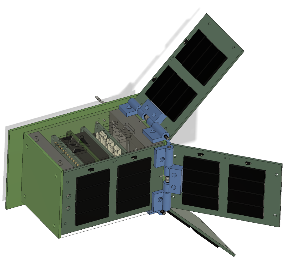
One of the primary considerations for the actuation mechanism was to minimize or eliminate the need for electrical energy, as conserving power is critical for the operation of picosatellites. To achieve this, a torsion spring was selected for the actuation mechanism. Torsion springs provide a reliable mechanical solution for deploying the solar panels without requiring continuous electrical power. The spring stores mechanical energy when twisted and releases it to deploy the panels when needed, ensuring a simple yet effective deployment system.
Deployment
The deployment process needed to be both stable and efficient to ensure the solar panels would deploy correctly and remain in position throughout the satellite’s mission. The design utilized a heating mechanism to release a binding thread that held the panels in their stowed position. When heated, the thread would break, allowing the torsion spring to deploy the panels. This method provides a controlled and reliable way to trigger the deployment at the appropriate time.
Space
Given the limited space available on a picosatellite, it was crucial to design the deployment system to fit within the permissible cross-section of 50 x 50 mm² when the panels are in their non-deployed condition. To optimize the use of space, the hinge thickness was minimized. This reduction in hinge size helps to ensure that the deployment mechanism can fit within the compact confines of the satellite without compromising structural integrity or functionality.
Fabrication
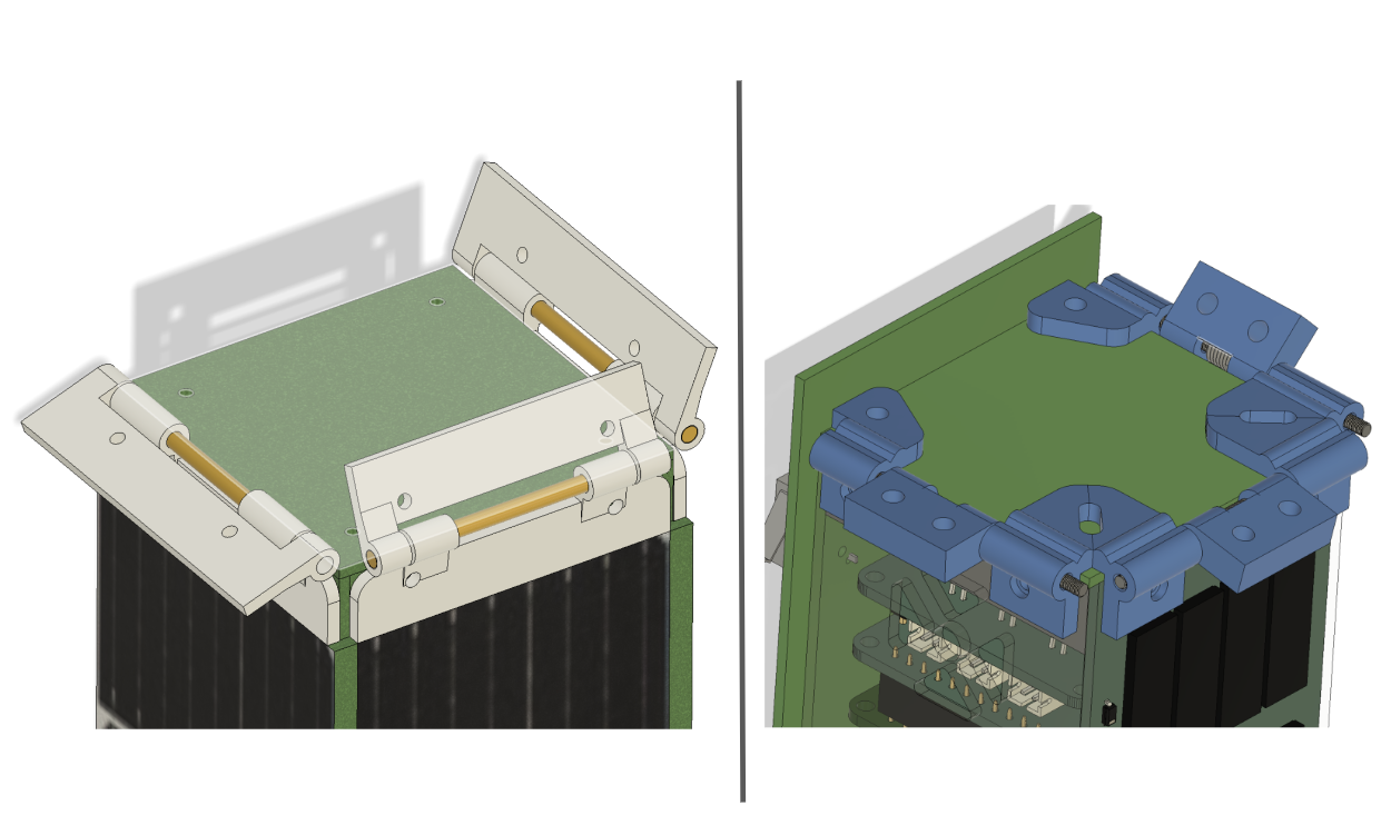
Ease of manufacture was another important consideration in the design process. The deployment system was designed with 3D printing in mind, allowing for rapid prototyping and cost-effective production of components. 3D printing offers the flexibility to produce complex geometries that would be challenging or expensive to manufacture using traditional methods.
Evolution of the Hinge Design
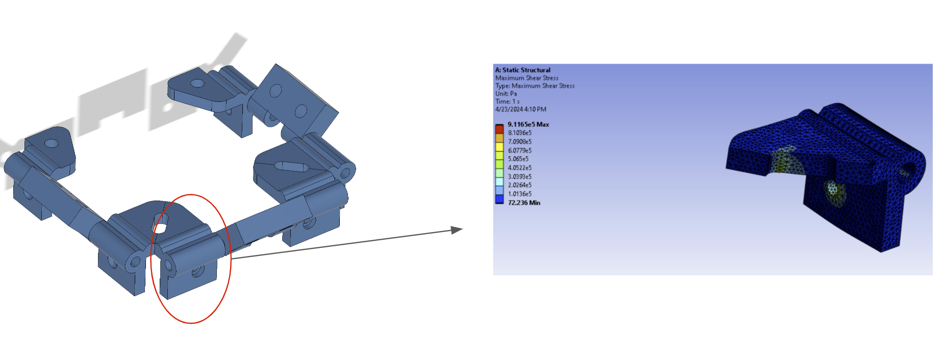
The hinge design evolved from thin and weak structures to thicker and stronger configurations.
- Thin Hinge: Space-efficient but weak when 3D printed.
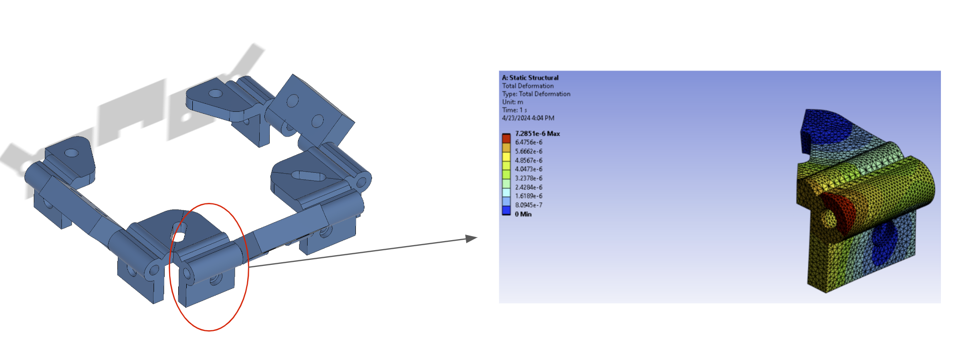
- Thick Hinge: Occupies more space but provides increased strength due to higher material concentration.
Finite element analysis (FEA) was used to verify the increased strength in the thick hinges.
Challenges and Customization
The hinge design was customized to minimize interference with other parts of the satellite or the deployer pod. The 3D printing process necessitated careful design adjustments to reduce shear force along the layer addition direction.
Shaft and Spring Design
Shaft
The shaft was designed using a 2 mm thick copper screw rod. The screw rod allowed the shaft to be locked in place with nuts on both sides of the hinges.
Spring
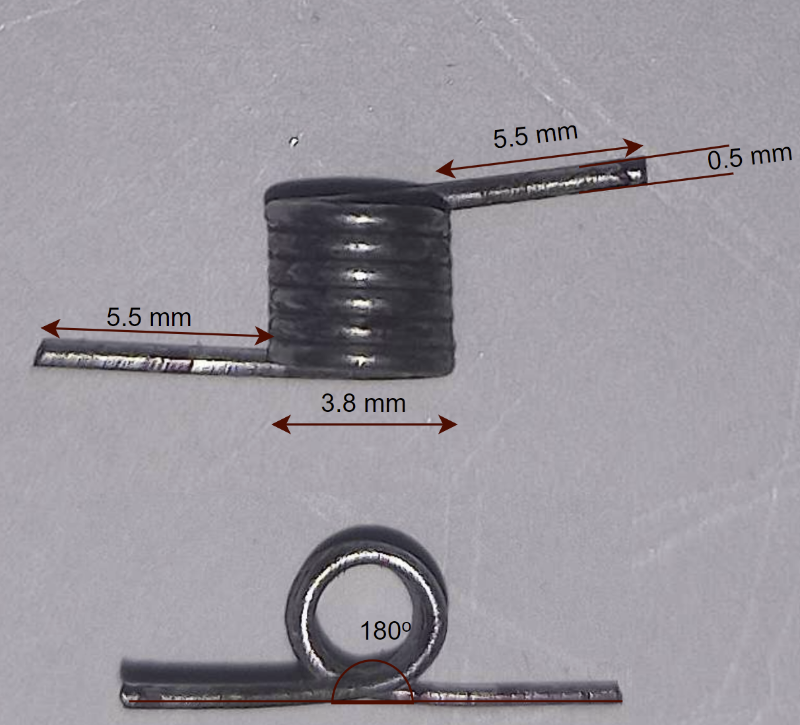
The design of the torsion spring was critical for effective deployment. The spring constant (k) was calculated using:
Where:
- (d = 0.5 , \text{mm}): Wire diameter
- (E = 200 \times 10^3 , \text{N/mm}^2): Modulus of elasticity
- (D_m = D_{\text{outer}} - D_{\text{wire}} = 3.8 - 0.5 = 3.3 , \text{mm}): Mean coil diameter
- (N_a = 6): Number of active coils
Torque and Force Calculations
The deflection angle (\theta) during the undeployed stage is (180^\circ = \pi , \text{radians}).
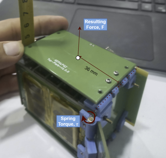
Force generated at the center of mass (C.O.M distance = 36 mm):
Gravitational force due to the panel weight ((19 , \text{g})):
Net upward force:
Assembly and Testing
The final system included:
- Hinges and springs: Manufactured and tested with 3D printing.
- Trigger mechanism: A resistor was used to heat and break the binding thread.
- Command integration: Deployment tied to the antenna deployment system, allowing a single command to deploy both.
The deployable system was validated through testing and ensured reliable operation within the constraints of the PocketQube satellite’s compact design.